

Applications
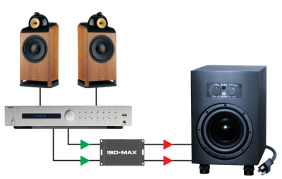
SUB-2RR in a HI-FI system
Connect the SUB-2RR right before your sub-woofer to eliminate hum and buzz problems in your hi-fi, audiophile or home theatre system.
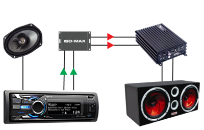
SUB-2RR in your car
The SUB-2RR isolates your car audio receiver system from your sub amp to eliminate nasty sounding ground loops. Locate next to the sub woofer amp for best performance.
Specifications
All levels are input unless noted, +4 dBu = 1.23 V RMS
| PARAMETER | CONDITIONS | MINIMUM | TYPICAL | MAXIMUM |
|---|---|---|---|---|
| Input impedance, Zi | 100 Hz, -10 dBV, test circuit 1 | 39.0 kΩ | 39.4 kΩ | 39.8 kΩ |
| Insertion loss | 100 Hz, -10 dBV, test circuit 1 | -0.30 dB | 0.00 dB | .30 dB |
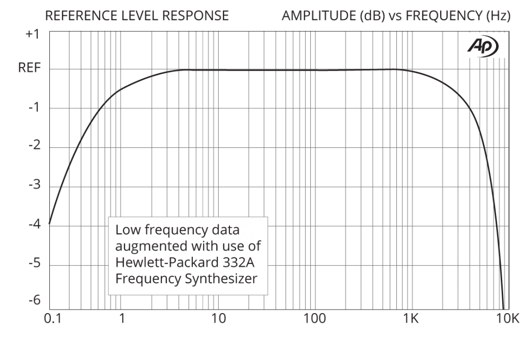
| Magnitude response, ref 100 Hz | 2 Hz, -10 dBV, test circuit 1 | -0.25 dB | -0.11 dB | -0.00 dB |
| Magnitude response, ref 100 Hz | 2 kHz, -10 dBV, test circuit 1 | -0.8 dB | -0.65 dB | -0.50 dB |
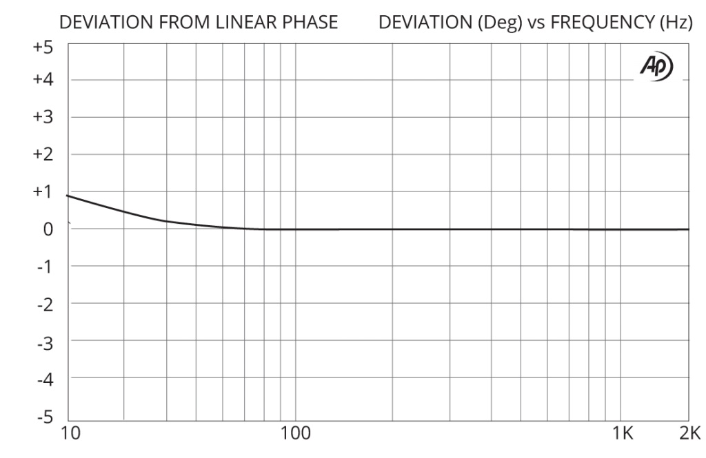
| Deviation from linear phase (DLP) | 10 Hz to 2 kHz, -10 dBV, test circuit 1 | +0.7/-0° | ±2.0° | |
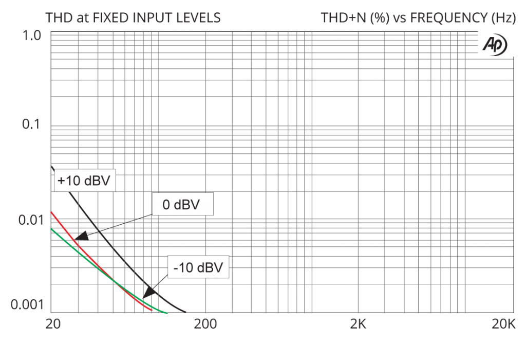
| Distortion (THD) | 100 Hz, -10 dBV, test circuit 1 | <0.001% | ||
| Distortion (THD) | 20 Hz, -10 dBV, test circuit 1 | 0.01% | 0.05% | |
| Maximum 20 Hz input level | 1% THD, test circuit 1 | +16 dBV | +18 dBV | |
| Common – mode rejection ratio (CMRR) | 60 Hz, test circuit 2 | 105 dB | ||
| Common – mode rejection ratio (CMRR) | 3 kHz, test circuit 2 | 50dB | 65 dB | |
| Output impedance, Zo | 100 Hz, test circuit 1 | 5.00 kΩ | ||
| Allowable source impedance | (output impedance of device driving the ISO-MAX input) | 0 | 600 Ω | 2 kΩ |
| Allowable load impedance | (input impedance of device loading the ISO-MAX output) | 20 kΩ | 47 kΩ | |
| Allowable load capacitance | (cable & input capacitance loading the ISO-MAX output) | 0 | 50 pF | 1000 pF |
| Optimal cable length | input | 3 m (10’) | 8 m (25’) | |
| Optimal cable length | output | 1 m (3’) | 3 m (10’) | |
| Temperature range | operation or storage | 0°C | 70°C | |
| Input to Output Voltage Difference* | input to output shield or either shield to chassis, 60 Hz | 24 V RMS 34 V peak |
Graphs
Phase Distortion (DLP)
Frequency Response
THD vs Level at Low Frequencies
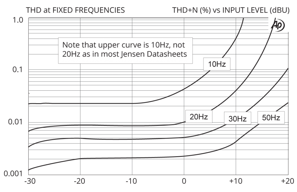
THD vs Frequency at Various Levels