

Applications
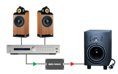
SUB-1RR in a HI-FI system
Connect the SUB-1RR right before your active sub-woofer to eliminate hum and buzz problems in your hi-fi, audiophile or home theater system.
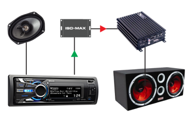
SUB-1RR in your car
The SUB-1RR isolates your car audio receiver system from your sub amp to eliminate nasty sounding ground loops as it delivers full, accurate bass.
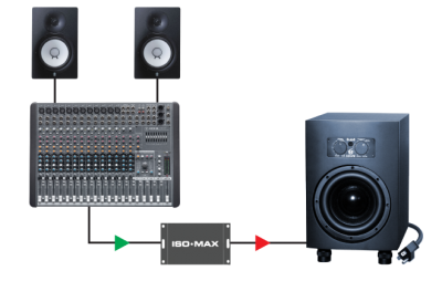
SUB-1RR in the studio
The SUB-1RR is the perfect interface to quiet down your monitoring system when recording. Pristine signal path assures a pure signal flow without artifacts.
Specifications
All levels are input unless noted, +4 dBu = 1.23 V RMS
| PARAMTER | CONDITIONS | MINIMUM | TYPICAL | MAXIMUM |
|---|---|---|---|---|
| Input impedance, Zi | 100 Hz, -10 dBV, test circuit 1 | 39.0 kΩ | 39.4 kΩ | 39.8 kΩ |
| Insertion loss | 100 Hz, -10 dBV, test circuit 1 | -0.30 dB | 0.00 dB | .30 dB |
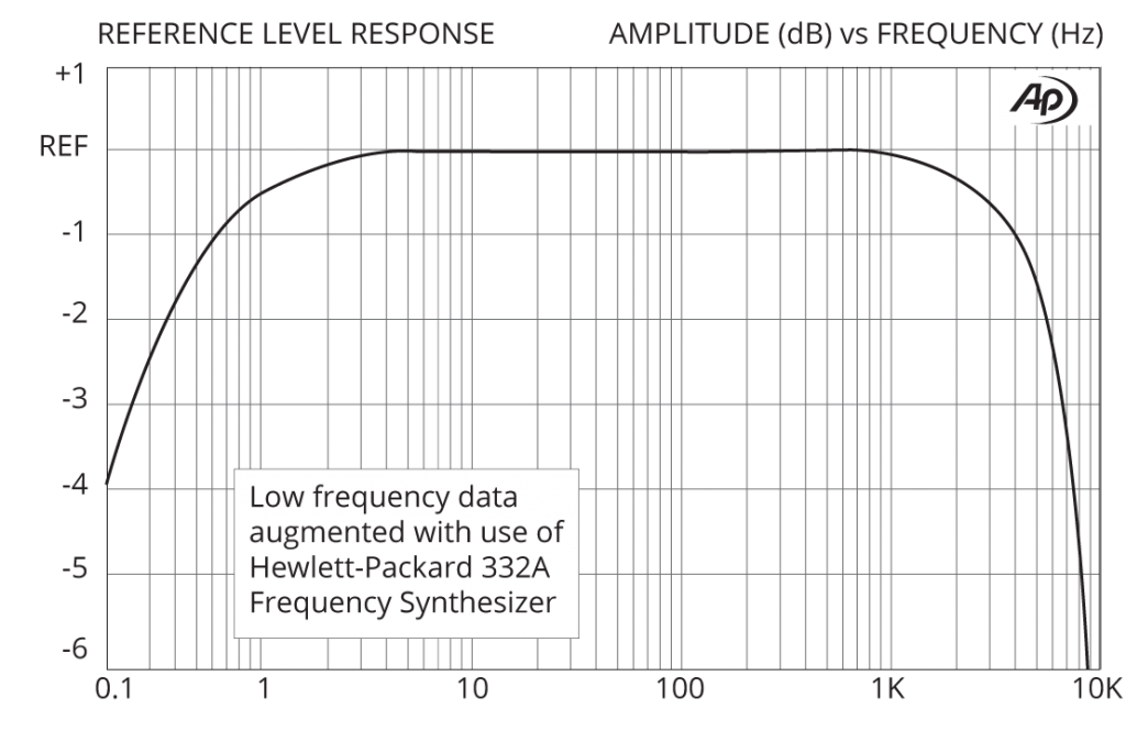
| Magnitude response, ref 100 Hz | 2 Hz, -10 dBV, test circuit 1 | -0.25 dB | -0.11 dB | -0.00 dB |
| Magnitude response, ref 100 Hz | 2 kHz, -10 dBV, test circuit 1 | -0.8 dB | -0.65 dB | -0.50 dB |
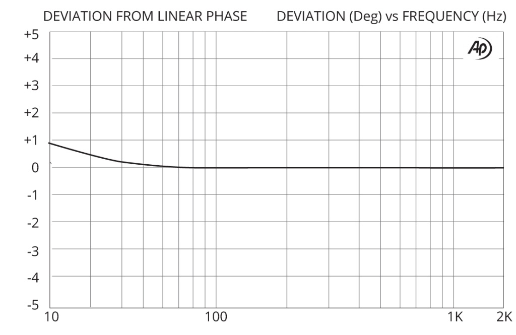
| Deviation from linear phase (DLP) | 10 Hz to 2 kHz, -10 dBV, test circuit 1 | +0.7/-0° | ±2.0° | |
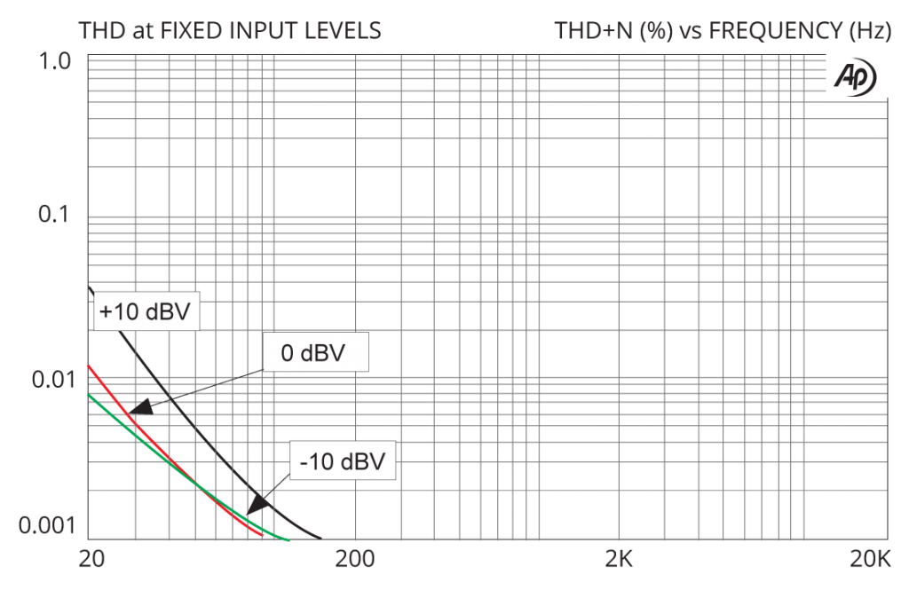
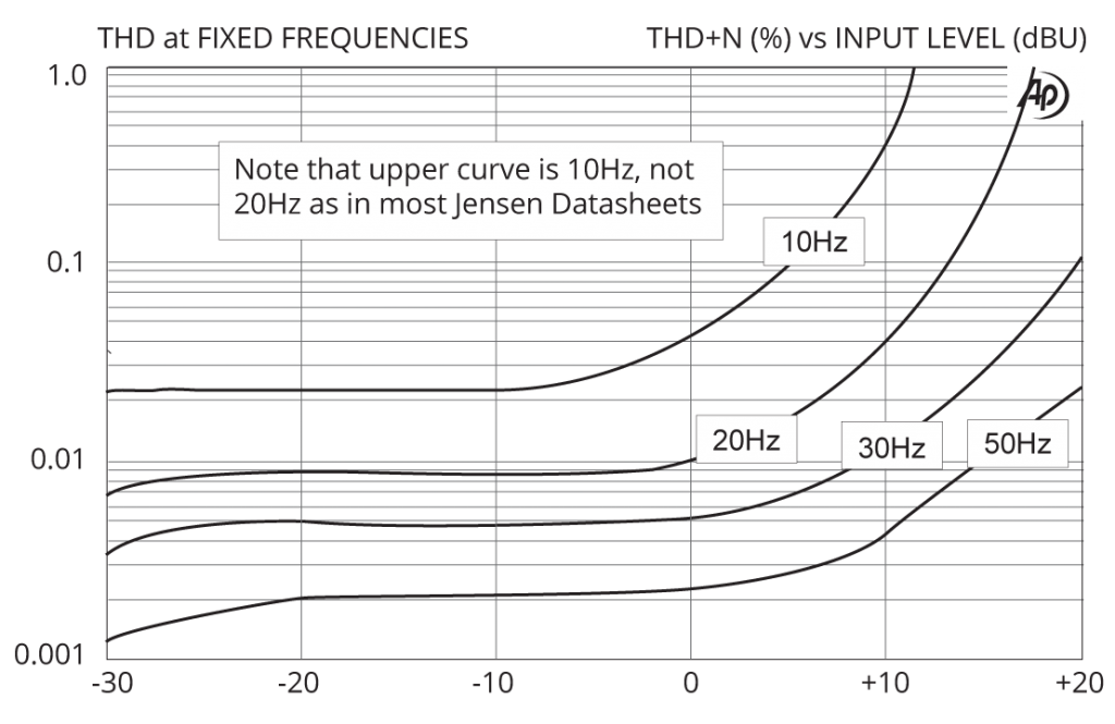
| Distortion (THD) | 100 Hz, -10 dBV, test circuit 1 | <0.001% | ||
| Distortion (THD) | 20 Hz, -10 dBV, test circuit 1 | 0.01% | 0.05% | |
| Maximum 20 Hz input level | 1% THD, test circuit 1 | +16 dBV | +18 dBV | |
| Common – mode rejection ratio (CMRR) | 60 Hz, test circuit 2 | 105 dB | ||
| Common – mode rejection ratio (CMRR) | 3 kHz, test circuit 2 | 50dB | 65 dB | |
| Output impedance, Zo | 100 Hz, test circuit 1 | 5.00 kΩ | ||
| Allowable source impedance | (output impedance of device driving the ISO-MAX input) | 0 | 600 Ω | 2 kΩ |
| Allowable load impedance | (input impedance of device loading the ISO-MAX output) | 20 kΩ | 47 kΩ | |
| Allowable load capacitance | (cable & input capacitance loading the ISO-MAX output) | 0 | 50 pF | 1000 pF |
| Optimal cable length | input | 3 m (10′) | 8 m (26′) | |
| Optimal cable length | output | 1 m (3′) | 3 m (10′) | |
| Temperature range | operation or storage | 0°C | 70°C | |
| Input to output voltage difference* | input to output shield or either shield to chassis, 60 Hz | 24 V RMS 34 V peak |
Graphs
Phase Distortion (DLP)
Frequency Response
THD vs Level at Low Frequencies
THD vs Frequency at Various Levels