

Applications
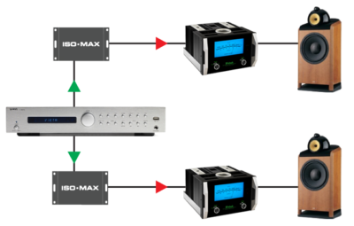
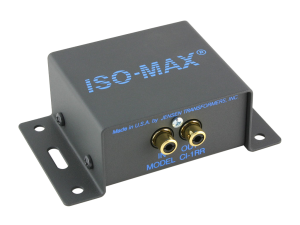
CI-1RR in a HI-FI system
Connect the CI-1RR in between your preamp and power amp to eliminate noise without affecting the signal quality. The CI-1RR’s exceptional frequency response, phase accuracy and signal handling makes it perfect for high-end 2 channel systems.
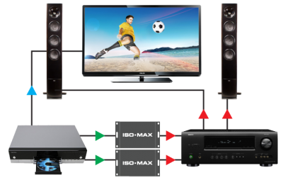
CI-1RR in a home theater
Combining video and audio together in home theater setups can often lead to noise. The Iso-Max CI-1RR solves the problem by isolating the video playback system from the multi-channel audio system, eliminating the hum and buzz caused by ground loops and DC offsets.
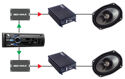
CI-1RR in a your car
Car audio enthusiasts know the challenges of ground hum polluting their audio. Turning up the volume only amplifies the problem. Isolating the radio/receiver from the power amp eliminates buzz caused by ground loops. The CI-1RR does it perfectly without affecting the performance.
Specifications
All levels are input unless noted, +4 dBu = 1.23 V RMS
| PARAMETER | CONDITIONS | MINIMUM | TYPICAL | MAXIMUM |
|---|---|---|---|---|
| Input impedance, Zi | 1 kHz, +4 dBu, test circuit 1 | 47.0 kΩ | 48.6 kΩ | 50.0 kΩ |
| Insertion loss | 1 kHz, +4 dBu, test circuit 1 | 0.82 dB | 1.0 dB | |
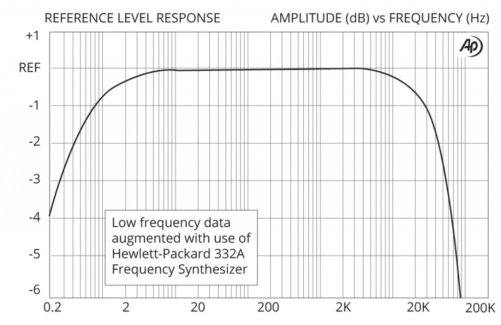
| Magnitude response, ref 1 kHz | 20 Hz, +4 dBu, test circuit 1 | -0.15 dB | -0.03 dB | ±0.0 dB |
| Magnitude response, ref 1 kHz | 20 kHz, +4 dBu, test circuit 1 | -1.0dB | -0.70 dB | ±0.0 dB |
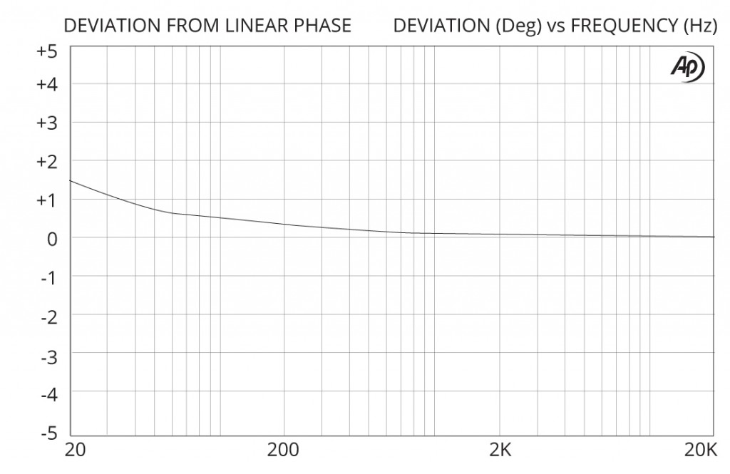
| Deviation from linear phase (DLP) | 20 Hz to 20 kHz, +4 dBu, test circuit 1 | +1.4/-0° | ±2.0° | |
| Distortion (THD) | 1 kHz, +4 dBu, test circuit 1 | <0.001% | ||
| Distortion (THD) | 20 Hz, +4 dBu, test circuit 1 | 0.04% | 0.10% | |
| Maximum 20 Hz input level | 1% THD, test circuit 1 | +17 dBu | +19 dBu | |
| Common – mode rejection ratio (CMRR) 600 Ω balanced / unbalanced source | 60 Hz, test circuit 2 | 95 dB | ||
| Common – mode rejection ratio (CMRR) 600 Ω balanced / unbalanced source | 3 kHz, test circuit 2 | 85dB | 85 dB | |
| Output impedance, Zo | 1 kHz, test circuit 1 | 4.65 kΩ | ||
| Allowable source impedance | (output impedance of device driving the ISO-MAX input) | 0 | 600 Ω | 2 kΩ |
| Allowable load impedance | (input impedance of device loading the ISO-MAX output) | 10 kΩ | 47 kΩ | ∞ |
| Allowable load capacitance | (cable & input capacitance loading the ISO-MAX output) | 0 | 50 pF | 100 pF |
| Optimal cable length | input | 3 m (10’) | 8 m (26’) | |
| Optimal cable length | output | 1 m (3’) | 3 m (10’) | |
| Temperature range | operation or storage | 0°C | 70°C | |
| Input to Output Voltage Difference* | input to output shield or either shield to chassis, 60 Hz | 24 V RMS 34 V peak |
Graphs
Phase Distortion (DLP)
Frequency Response
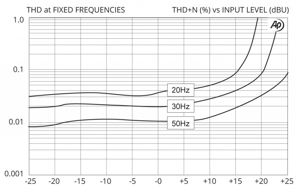
THD vs Level at Low Frequencies
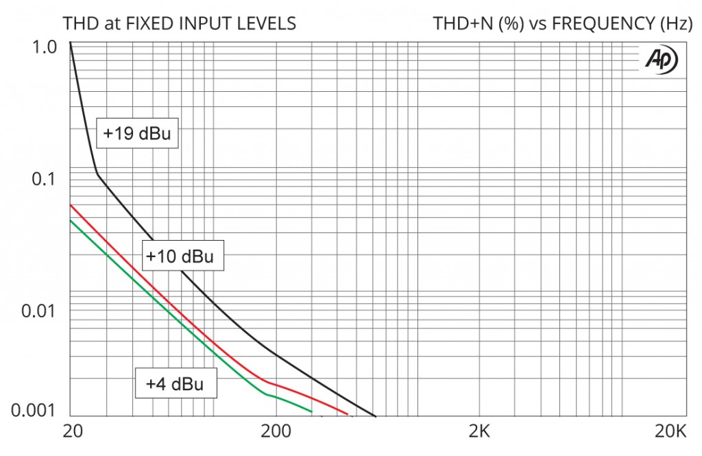
THD vs Frequency at Various Levels